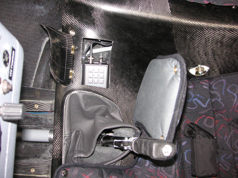
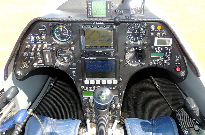
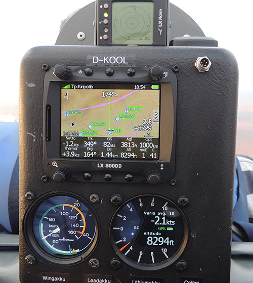
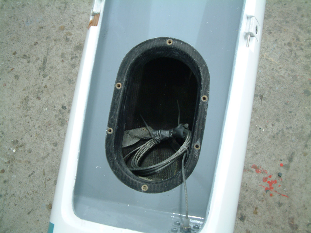
Radio/Transponder: Becker Transponder: ATC3401 and a Garrecht Mode S Transponder: VT-01 are fitted. Transponder is Mode "S" Refer to http://www.eurocontrol.int/mode_s/ for details. Main unit is fitted mid fuse >> , >> below engine compartment, aerial is internally mounted in central fin area, access behind rudder. Panel display operates main unit remotely. A dongle is required to provide altitude encoding, ordered but not yet received. 2 x Sennheiser H100 headsets (they double as noise defenders) connect to the AR4201, via sockets mounted under the rear panel (see picture below). This will provide intercom and radio when the engine is running. A switch on the front panel selects Headset or Speaker. A PTT switch is fitted to the top of each stick along with a sidewall mounted boom mic. Flight Computer: The LX8000 is fitted centrally on front panel with LCD vario display to right. The LX8000D is fitted on rear panel with LCD vario above. The L8000 has an integrated FLARM processor which displays to an LCD display, coaming mounted front and rear, a voice module and an SD card reader. Logger: The LX8000 has an integral IGC logger which can be downloaded directly to a USB stick or an SD memory card. The LX8000D also has an integral logger which can be downloaded to an SD card, but is not IGC approved. A Colibri logger is fitted under a flap on the rear seat. This provides for an independant flight computer and navigation functions should the LX8000 fail. LX8000 Logger: Serial number JF8 (25172) calibrated 2010. Colibri Logger: Serial number CDM (16042) calibrated 3.8.2009 EFIS: A Dynon D101A electronic flight information system is centrally mounted on the front panel. It provides an extremely accurate Attitude Indicator and True Heading display, with Altitude and Speed tapes, a Slip Indicator and additional display of millibar setting in use. It is functional on switch on and usable within 10 seconds when the display changes from black and white to full colour. It also has an internal backup battery in the event of external power failure. Logger Compartment:
Oxygen: A 4 litre Oxygen bottle is fitted on the upper fuselage right side above spar. It utilises a bracket at the neck and a spherical recess on the rear bulkhead to hold the round base to the bottle. An electronic digital pulse demand Mountain High twin outlet system, EDS Model O2D2, utilising simple personal cannular attachments provides an economical Oxygen system for use up to 18000'. PLB(personal Locator Beacon): A seperate McMurdo Fast Find PLB210 is carried in the front side pocket. It features a GPS and syndicate members details are stored on an International database. Fuel Tanks: The centre tank holds 19 litres and has a contents display on the ILEC panel. The 2 wing tanks have a capacity of 30 litres each but no contents information. A panel mounted switch opens a valve to feed wing fuel into the centre tank. This MUST be monitored carefully since this fuel will vent overboard once the centre tank is full! Flow rate into centre tank is greater than engine consumption at full power. Fuel Pump: The fuel pump fitted to the centre tank will facilitate refuelling of the centre tank. Batteries: The normal battery set up is system A;4 sets of sealed Lead acid cells, 2 stowed in the fin and 2 stowed mid fuselage produce a total of 30 A/H at 12V, system B; 2 sets of NiMh batteries, stowed in the outer wing leading edges, producing 30 A/H at 12V. Engine battery power is provided by twin LiMn (Lithium Mangan accumulators) 8.8 A/H 14V sets. Operating voltage is 12V - 16.8V. They are fitted in the ceiling of the fuselage behind the rear pilot. These batteries can be recharged by an external electronic charger and/or by solar power if selected, see below. After a typical engine start sequence, the battery packs will be completed recharged with 1 hour of typical solar power input. A 7.5A/H 12V battery can be fitted in the front storage box to power system A if the fin batteries are removed for solo flight. This can be used in conjunction with the rest of system A. 4 Solar panels are fitted. 2 control switches on the front panel will direct all solar energy to system A or the LiMn engine batteries. The LX8000, Radio, Transponder and EFIS can all be powered by either A or B system by selecting Up(A) or Down(B) respectively on the front panel. Additionally all power switches have a centre OFF position. System A will power; Colibri logger (on power connection, no switch), engine electric fuel pump, engine water pump, electric refuelling pump, electric trim motor and various relays. Access for charging all battery sets is provided on the left side of the rear panel. Access ports can also be used to provide power, except the LiMn port. Paint Scheme: Dark Blue is RAL 5002, Light Blue is RAL 5012. Instrument Panels:
|